section background img

Line Heaters

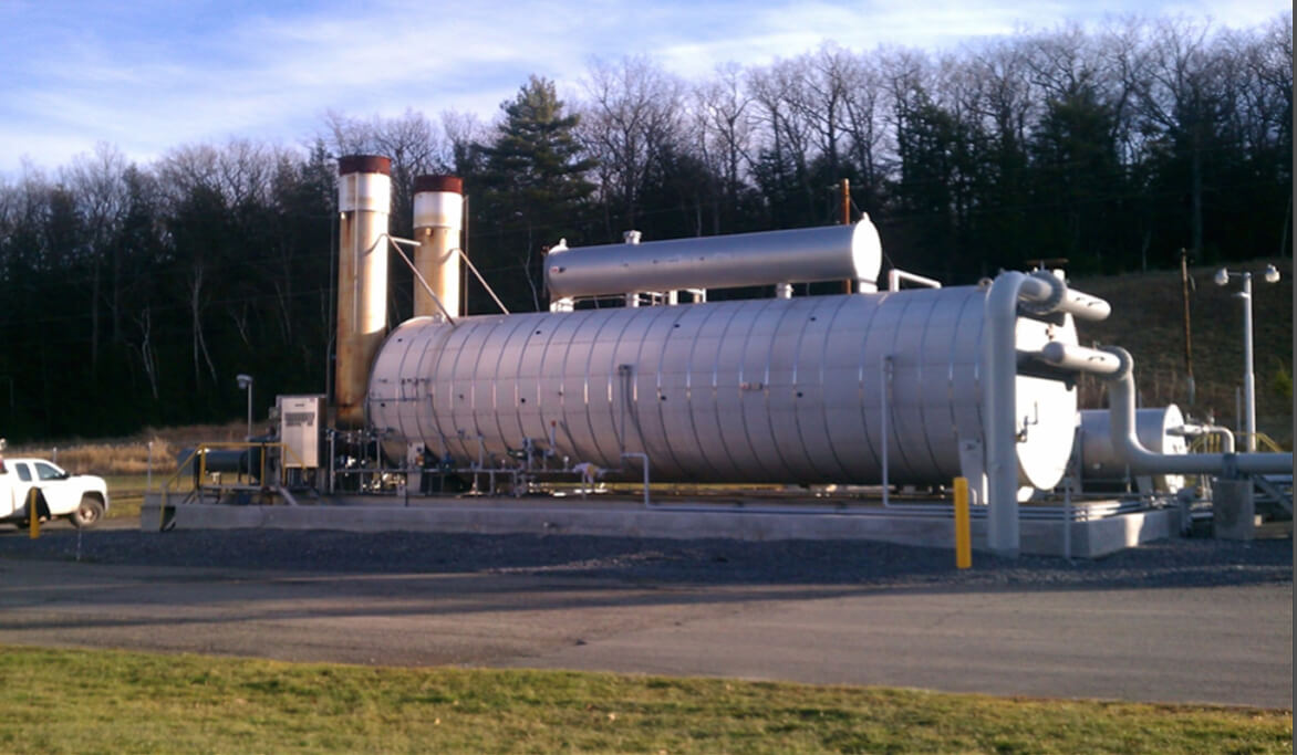
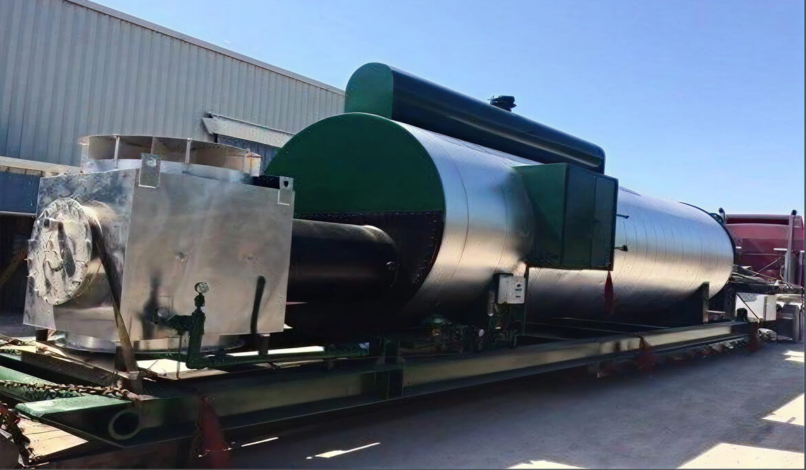
Indirect Heaters have a long history of successful application in the
oil and gas industry. The Indirect Heater consists of three basic
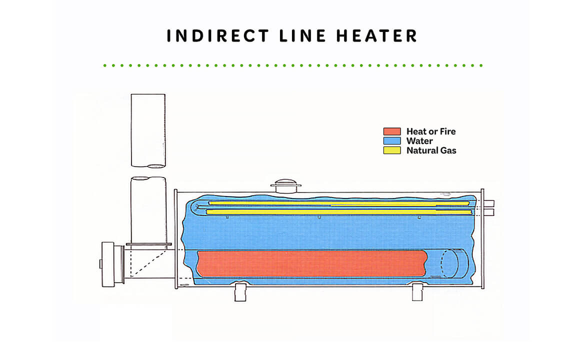
elements: the firetube, the heater bath shell, and the process coil.
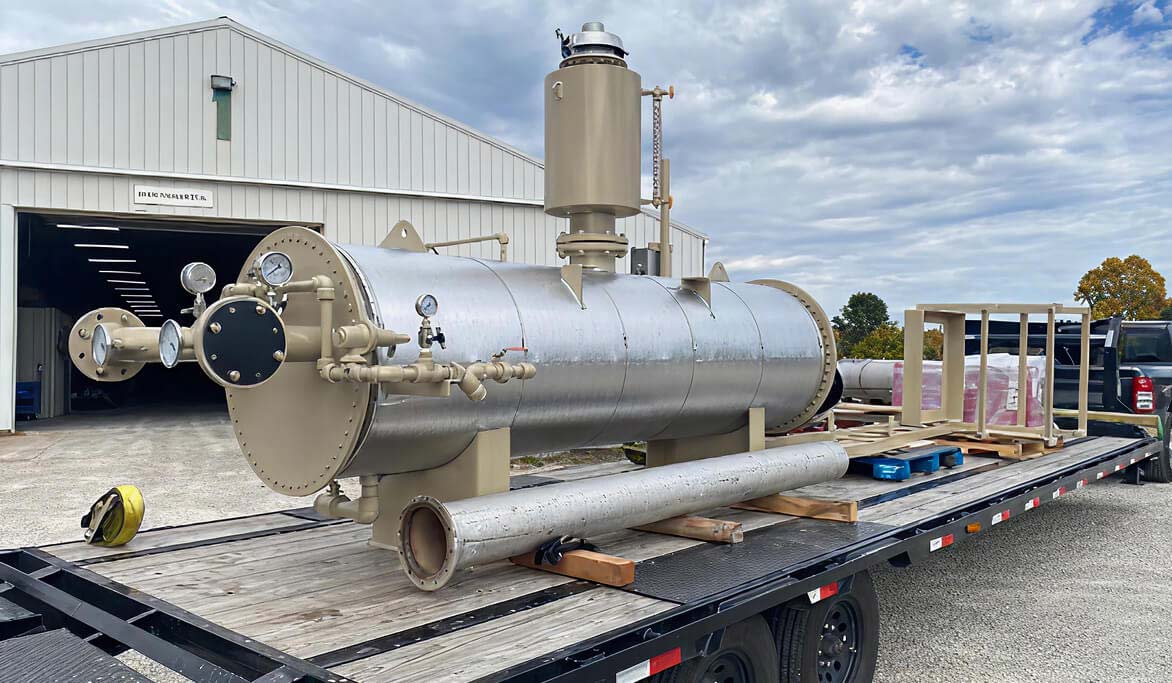
These three elements work together for the processing and
transmission of oil and gas by providing heat to the process fluid
for prevention of low temperature process problems and
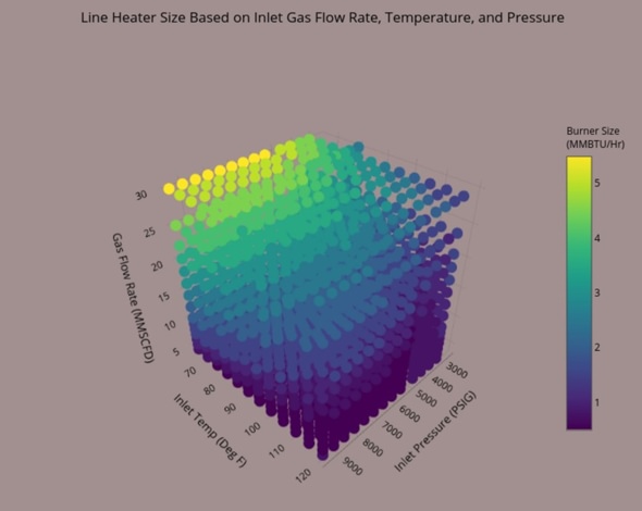
inefficiencies in downstream operations. Cimarron Indirect Heaters
come as standard sizes based on required BTU/Hr heat input to the process fluid. However, most process coils are sized/designed for the individual requirements of the specific application.

Models

Cimarron offers standard design Water Bath & Glycol/Water Bath Indirect Heaters based on BTU/Hr Heat Input Required

  • BTU/Hr ranges include 0.25 to 2.0 MM BTU/Hr Heat Input (24”OD x 7’-6”E/E to 60”OD x 17’-6” E/E)
  • Customized designs for up to 10MM BTU/Hr Indirect Heaters (96” x 30’)
  • Coils are individually designed for each application to meet process requirements

Markets & Applications

  • Wellhead Line Heaters
  • Gas Production Unit (Combo Separator/Indirect Heater)
  • Midstream Gas Conditioning: Compressor Stations
  • Gas Transmission
  • Expert Engineering

    Our in-house process and design engineering team has over 100+ combined years of experience in plant, field, and facility Indirect Heater applications. We use industry accepted tools to size our units.

  • Application Designs

    We can offer a variety of Indirect Heater designs to meet a customer’s specific requirements; ex.; ASME Code Coil Design; Multi-path, Multi-pass coil design.

  • Advanced Controls

    We offer a full spectrum of fuel gas and process controls options from pneu­matically powered (electricity free) units to fully auto­mated PLC options with in-house I&E design team.

  • Comprehensive Field Services

    We have a dedicated in-house service team with extensive Indirect Heater commissioning, operating, and troubleshooting experience in most major basins. Rest assured that Cimar­ron will be available to support the product throughout its life.

  • Sytelink360® Real-Time Monitoring

    Our real-time monitoring system, Sytelink 360®, helps optimize equipment performance and predict failures while providing data-logging capability on the cloud.

Technical Information

Expand sections below to see more information. If you’d like even more details, be sure to check out full Technical Library below.

  • How It Works

    • Fuel gas is burned within the horizontal “U” -shaped firebox immersed in the lower portion of the water bath. Heat released by the burning fuel gas is quickly transmitted through the firebox wall to the water bath, maintaining it at desired temperature.
    • The fluid to be heated (wellstream, natural gas, oil, water, etc.) is conducted through the flow coil of the heater which is immersed in the upper portion of the water bath. Heat is transmitted from the hot water bath through the tube-wall to the fluid inside the flow coil.
    • The heater temperature controller maintains the bath typically between 180°F and 195°F such that fluid in coil stays above hydrate formation temperatures. Greater than 195°F temperatures cause bath losses.
    • Sizing is based on fluid composition such that fluid is heated adequately enough to stay above hydrate formation temperatures. The firetube size is a function of heat duty required to maintain fluid temperatures above required outlet temperatures.
  • Additional Technical Information

    Applications Expanded:

    • Heating natural gas prior to regulation to prevent formation of frost rings around the buried line downstream of the regulation station.
    • Heating high pressure natural gas prior to pressure reduction to prevent the formation of natural gas-water hydrates in the line downstream of the choke or regulator.
    • Heating a natural gas-condensate wellstream prior to separation, with or without an associated pressure reduction, so as to control the separation temperature, prevent the formation of hydrates, and assure good gas-liquid separation.
    • Heating of crude oil to maintain temperature above paraffin pour-point and to reduce its viscosity for easier handling in further lease processing.
    • Heating glycol for use in heat tracing applications.
    • Heating a natural gas wellstream to maintain it above its hydrate-forming temperature from the well to the processing point even though reduction of wellstream pressure is minimal.
    • Typically designed in accordance with API 12K specification
  • Design Parameter Considerations

    • Inlet Pressure (PSIG): Typically between 500 and 5000 psig
    • Inlet Temp (°F): Typically between 40-120°F
    • Gas Inlet Flowrate (MMSCFD): Typically between 5-20MMSCFD
    • Gas Outlet Temp (°F): Typically between 70-120°F
    • Gas Outlet Pressure (PSIG): Typically below 1000 psig
    • Inlet Gas Composition required to determine hydrate formation temperatures.
  • Sizing Charts

Want More Information?

For more documentation on all Cimarron’s products visit the Technical Library.

View Our Technical Library