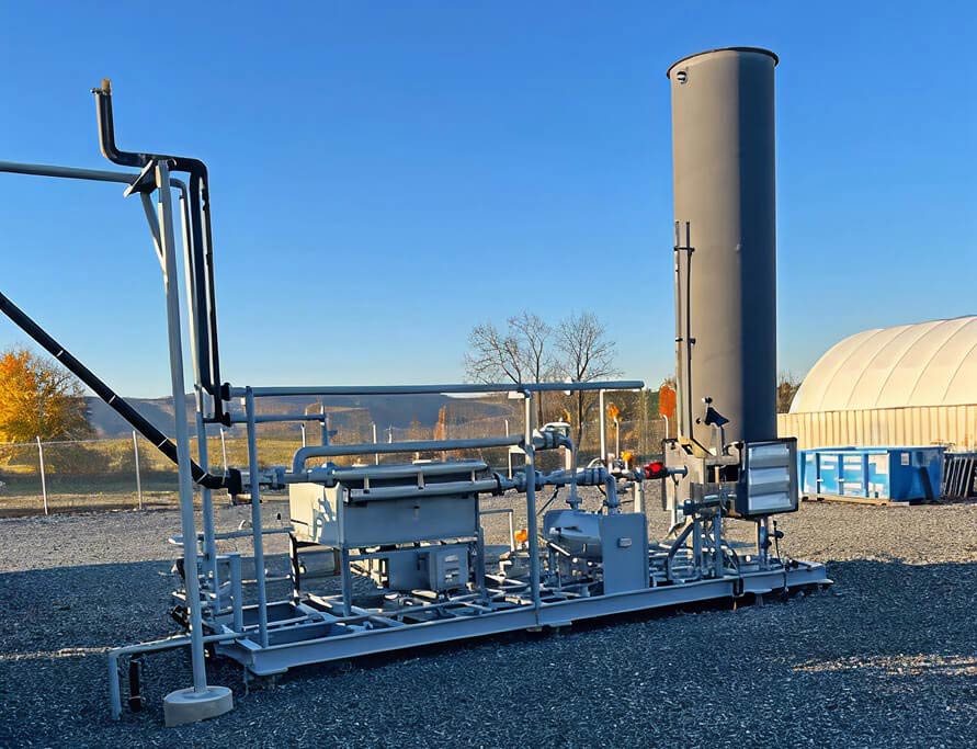
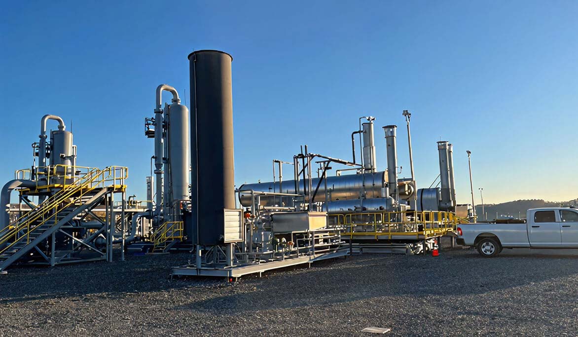
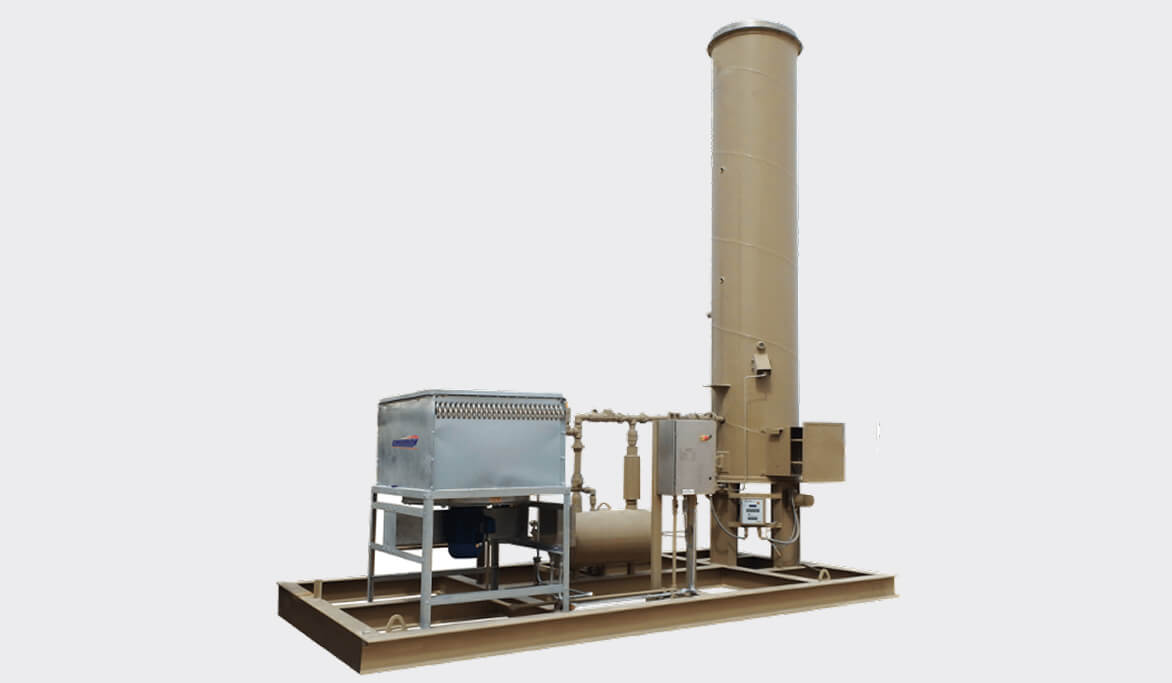
section background img

BTEX Mitigation Systems

Emissions from a glycol dehydration systems contain harmful VOCs. Environmental regulations and momentum from operators to eliminate all harmful emissions to atmosphere have created an increased need to find the best approach for solving this issue.

Models

  • Condensers

    • Air-cooled
    • Forced draft
    • Glycol Cooled
  • Combustion System

    • Enclosed and Open
  • Compression based recovery systems

Markets & Applications

  • Upstream natural gas processing sites
  • Midstream natural gas transmission
  • Only company that offers both the TEG and BTEX system, fully integrated with each other.

    We offer companion products that are fully integrated into our dehydration units to eliminate BTEX emissions such as A-Frame and Forced-Draft condensers and 10 EPA OOOOb certified Enclosed Combustors models guaranteed at 98% DRE. We can also provide an emissions analysis upon request. Cimarron’s advanced knowledge of Gas Dehydration Systems and Combustion/Flaring is unmatched in the industry when comparing to fabricators with only one line of product expertise.

  • Advanced Controls

    We offer a full spectrum of controls options from pneumatically powered (electricity free) units to fully automated PLC options with in-house I&E design team.

  • Comprehensive Field Services

    We have a dedicated in-house service team with extensive dehydration commissioning, operating, and troubleshooting experience in most major basins. Rest assured that Cimarron will be available to support the product throughout its life.

  • Sytelink360® Real-Time Monitoring

    Our real-time monitoring system, Sytelink 360®, helps optimize equipment performance and predict failures while providing data-logging capability on the cloud.

Technical Information

Expand sections below to see more information. If you’d like even more details, be sure to check out full Technical Library below.

  • How It Works

    Glycol dehydration systems commonly use Tetraethylene Glycol (TEG) to absorb water by contacting saturated gas via an absorber tower. The glycol water mixture, or rich glycol stream, is heated in a reboiler vessel where the water plus absorbed residue gas vapors are flashed off the lean glycol. Along with the water vapor, there is GHGs such as methane and trace amounts of VOCs and HAPs. In the past these vapors were vented directly from the reboiler stack to the atmosphere, it is now becoming more common place to destroy or mitigate these.
    Destruction versus Recovery? Determining which path to BTEX removal is often one governed by regulatory requirements and economics. Federal regulations may require a BTEX removal device for every new installed TEG dehydration system. State regulatory agencies may require more or less emissions requires, driving the operator to consider the entire site wholistically when determining what their needs and requirements are for BTEX mitigation.

    • Destruction:
      • Regen Reboiler Burner: The reboiler vapor stream can routed to the reboiler burner and mixed with fuel gas in a proprietary mixing chamber to be destructed by the reboiler burner during “burner on” cycle in the glycol reboiler During “burner-off” cycle, the vapors are routed to a glow plug in the exhaust stack.
      • Dedicated Combustor: Due to the issues above, and ability to fit combustor design for BTEX applications purposes, a dedicated combustor is the recommended route for BTEX removal. Current technologies allow for up to 99% and greater destruction efficiency across most turndown conditions.
    • Recovery:
      • To move gas into a sales line, some form of compression must be used, typically via screw VRUs. The BTEX residue gas still contains a significant amount of water vapor, even post condenser. Without complete water removal of this stream, mechanical VRU recovery via screw compression is difficult. It is difficult to handle varying water contents resulting from turndown. If not sized appropriately oil lubricated screw compressors suffer operability issues from condensed water in the discharge stream.
  • Process Information

    Potential Waste Streams from a TEG Dehydrator

    • Vapor Stream from Reboiler Still Column: Commonly contains 90%+ water/residue gas mixture.
    • Flash Gas Stream: Other wise known as pump gas. On TEG glycol dehydrators, rich return glycol contains residue gas from contact with gas in the absorber tower as well as gas that is used to power pneumatically operated energy exchange pumps on the regenerator itself. This gas is often used to power pneumatic instruments as well as the reboiler burner. It can also be used as stripping gas to be introduced in the reboiler via a sparger tube or box.
    • Stripping Gas Stream: This is typically cool, wet, methane gas that is introduced into the reboiler unit via a sparger tube submerged in the hot glycol that bubbles this gas in the glycol. It is used to reduce partial pressure of the water to more efficiently flash to vapor.

    Condensing: Commonly the water, BTEX gases, and other VOC present in the vapor stream are first sent to a condenser.

    • Ambient Air Cooled: These condensers can be either natural or force draft and utilize ambient air to cool the vapor stream. The condensing temperature is however limited to ambient conditions. In warmer climates this limits the vapor outlet temperature and thus the effectiveness in condensation. In cooler climates, these units can be prone to freezing if not properly winterized using heat tracing or cold weather enclosures.
      • Natural: Comprise of multiple fin tubes depending on vapor flow rate. Plus: No electrical power required. Minuses: Large footprint. Fins can be prone to fouling and natural conditions.
      • Force Draft: Vapors are sent through fan cooled tube bundle to condense. Plus: Smaller footprint, typically better approach in warm weather environments. Minus: Requires electrical power. Moving parts.
    • Glycol Cooled:
      • Shell and Tube: Cooled, rich glycol from contactor tower is cross exchanged in shell and tube exchanger with hot overhead vapors. Outlet temperatures are typically at or above ambient temperatures. Plus: Efficient use of waste heat. Better control of condenser outlet temperature. Minus: Cost, fouling of exchanger tubes.
  • Design Parameter Considerations

    Corresponding Gas Dehydration Unit process data is used to determine the size of the BTEX Eliminator System. The following considerations are necessary to determine additional features required for the BTEX Eliminator System:

    • Does the dehy unit have a Pump (Flash) Gas Separator? Determines the quantity and need to mitigate flash gas emissions from dehydration system.
    • Is pump gas used as regen fuel gas? Determines the quantity of flash gas that may need to be destructed in conjunction with the still column vapors BTEX stream.
    • Is pump gas to be destructed in BTEX Destroyer unit? Determines the quantity and need to mitigate flash gas emissions from dehydration system.
    • Is the dehy unit using stripping gas? An additional stream of waste gas that must be added to still column vapors flow rate.
    • Is clean assist gas available (>1000BTU/scf)? May be needed if application requires enrichment to fully combust.
    • Is electricity available on site? Determines if a force draft condenser may be used.

Want More Information?

For more documentation on all Cimarron’s products visit the Technical Library.

View Our Technical Library