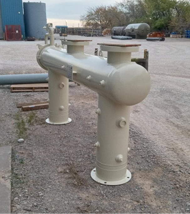
section background img

Filtration

Configured either as a vertical or horizontal vessel, filters work to remove solids and liquids (usually consisting of water, oil, compressor oil, and/or aerosols from the gas stream) to protect downstream equipment. Allows natural gas to be utilized for a particular application or undergo further processing.

Models

  • Vertical Coalescers

    • Standard sizes up to 54”ID+, 200MMSCFD+
    • Custom designs
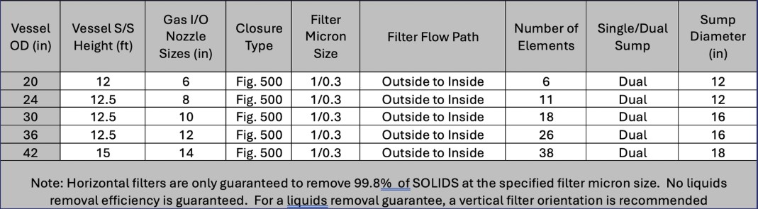
  • Horizontal and Vertical Filters

    • Standard sizes up to 54”ID+, 200MMSCFD+
    • Custom designs

Markets & Applications

  • Upstream Gas Processing
  • Midstream transmission
  • Downstream Refineries and Plants
  • Typically combined with Gas Dehydration
  • Compressor Stations
  • Fuel Gas Conditioning
  • Expert Engineering

    Our in-house process and design engineering team combined with experienced sub-vendors allows Cimarron the flexibility to provide the solutions that customers require for their applications.

  • Filter Accessory and Skid Packaging Option

    Typical accessories shipped loose for customer installation in the field can be provided. Cimarron can also provide fully functional skid packaging with instruments, controls, and piping in accordance with customer requirements, allowing the customer flexibility in transporting.

  • Sytelink360® Real-Time Monitoring

    Our real-time monitoring system, Sytelink 360®, helps optimize equipment performance and predict failures while providing data-logging capability on the cloud.

  • Comprehensive Field Services

    We have a dedicated in-house service team with extensive dehydration commissioning, operating, and troubleshooting experience in most major basins. Rest assured that Cimarron will be available to support the product throughout its life.

Technical Information

Expand sections below to see more information. If you’d like even more details, be sure to check out full Technical Library below.

  • How It Works

    Vertical Gas Coalescer Filter

    A typical 2-stage vertical coalescer filter has two main compartments: filter section and sump section. In this configuration, the gas flows into to the lower sump section and impinges upon an inlet diverter, free liquids drop out to the bottom of the vessel and exit via the sump liquid outlet nozzle. The gas travels vertically through tube-sheet perforations up through the attached filter cartridges, then exits the elements into the upper chamber of the vessel, and out through the gas outlet nozzle. As the gas passes through the cartridge(s), liquids will coalesce on the cartridge and fall to the bottom of the filter section, then exit vessel through the filter section liquid outlet nozzle. Filter access to change out filter cartridges is provided via the full body closure as the top head.

    Horizontal Filter Separator

    A typical 2-stage horizontal filter separator has three main compartments: 1st stage section, 2nd stage mist extractor (wire mesh pad or vane type) section, and sump section. In this configuration, the gas flows into the filter section and impinges upon risers (filter pipe supports on the tube-sheet), free liquids will drop out to the bottom of the vessel filter section. As the gas passes through the cartridges up through the tube sheet, into the mist extractor section, it will coalesce on the outside of the cartridge and drop to the bottom of the vessel. The gas passes through the mist extractor section that further coalesces the liquids on the wire mesh or vanes prior to exiting the vessel through the gas outlet nozzle. The liquids flow down to the vertical sump sections of each stage, or a single vertical sump on the 2nd Stage. If a horizontal sump design, each stage has a downcomer pipe that passes the liquid to a horizontal partitioned sump. Liquid exits through the corresponding liquid out nozzles. Filter access to change out filter cartridges is provided via the full body closure as one of the side heads.

  • Design Parameter Considerations

      Inlet Gas Flow Rate: Usually expressed in MMSCFD

    • Gas Specific Gravity or Molecular weight
    • Inlet Operating Pressure: Usually expressed in PSIG.  The lower pressure combined with higher flow rate will increase the vessel diameter.
    • Inlet Gas Operating Temperature: Usually Expressed in Fahrenheit.
    • Liquid Flow Rate: Usually expressed in BPD or gallons.  Usually low amount.
    • Type of liquid(s): Water, oil, lube oil, glycol, etc.
    • Type of solid(s): Scale, rust, etc.
    • Efficiency: Usually expressed as follows.  Note that typical common cartridges are usually 1% micron or 0.3% micron.
      • Example efficiency: Liquids removal XX.X% of X micron and larger
    • Gas Analysis if available
  • Sizing Charts

Want More Information?

For more documentation on all Cimarron’s products visit the Technical Library.

View Our Technical Library