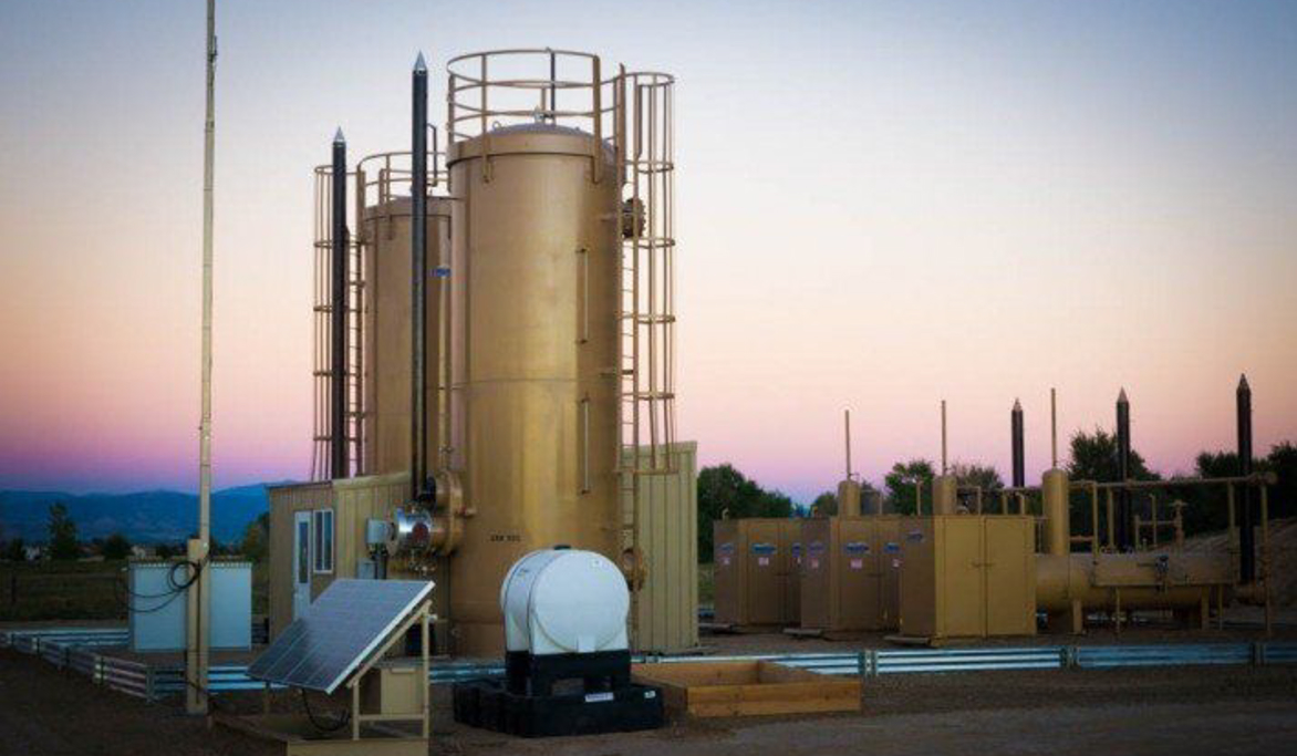
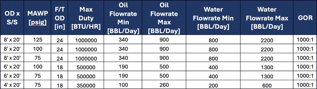
section background img

Heated Treaters & Separation

Removal of water from crude oil is called “oil dehydration” or “oil treating”.  Treaters are the vessels that accomplish this task.  One of the processes for “oil treating” is adding heat to the oil/water mixture to facilitate the removal/separation of water from oil.  Heater Treaters have a long history of successful application in the oil and gas industry.  The Heater Treater comes in one of two vessel “orientations”; vertical or horizontal.  Both Heater Treater orientations consist of three sections: Inlet/Degassing Section, Heating Section, and Outlet/Coalescing Section.

Models

  • Vertical Treaters

    • 0.25 to 1.0 MM BTU/Hr Heat Input (4’OD x 20’S/S to 8’OD x 20’S/S)
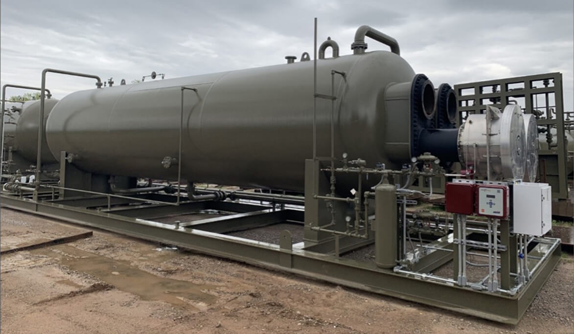
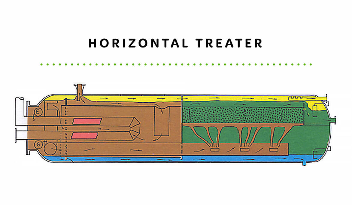
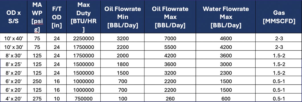
  • Horizontal and Horizontal Treaters

    • 0.75 to 2.25 MM BTU/Hr Heat Input (4’OD x 20’S/S to 10’OD x 40’S/S)
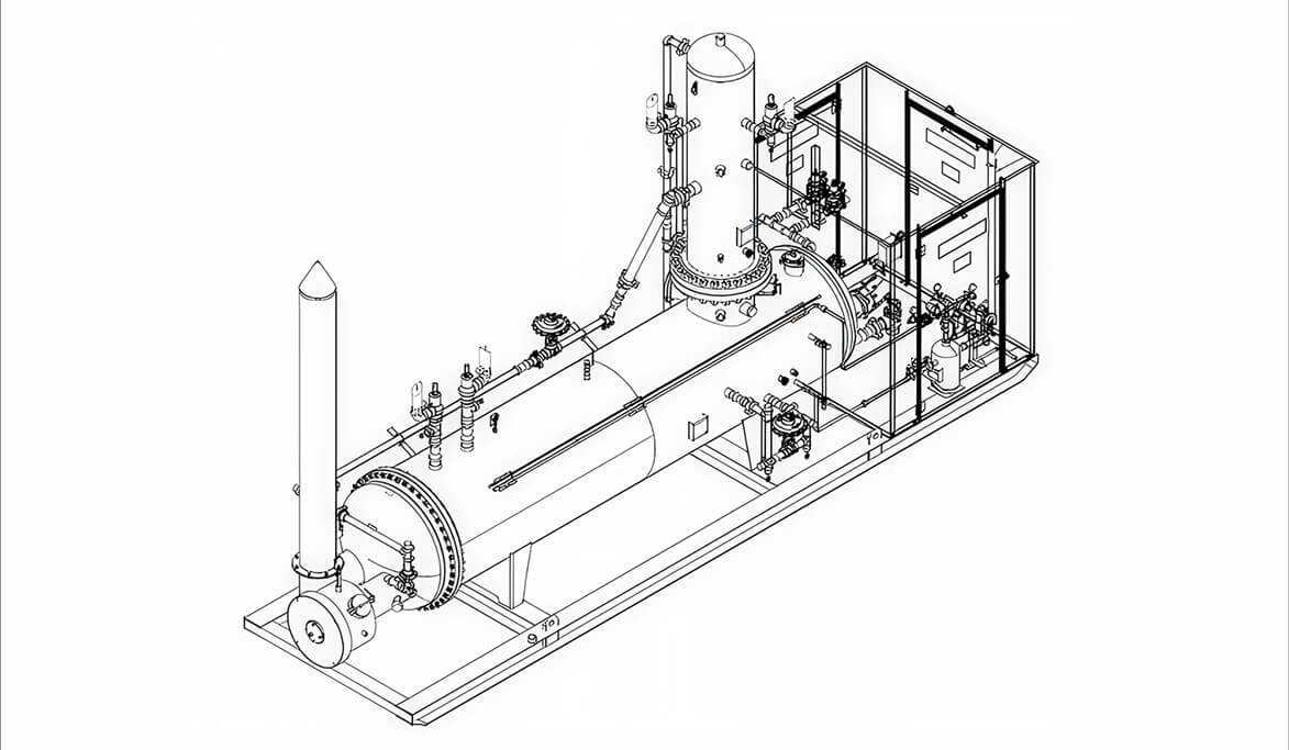
  • High Low Package

    • 48”OD x 16’ LP Heater, 24” OD x 96” HP Gas Vessel

Markets & Applications

  • Vertical Treater Applications:

    • Small capacity applications with flow streams containing high % of water.
    • Standard designs recommended for medium to high API gravity oils.
    • Treated oil will typically contain 0.5-0.2% BS&W for 20-50 API Gravity oils respectively.
  • Horizontal Treater Applications:

    • Relatively high crude flowrate capacity applications with small to medium amounts of water
    • Recommended for 10 API and higher gravity oils
    • Treated oil will typically contain 0.5-0.1 percent BS&W for 20-50 API gravity oil respectively
  • Expert Engineering

    Our in-house process and design engineering team combined with experienced sub-vendors allows Cimarron the flexibility to provide the solutions that customers require for their applications.

  • Heated Separation Equpiment Packaging Options

    Typical accessories shipped loose for customer installation in the field can be provided. Cimarron can also provide fully functional skid packaging with instruments, controls, and piping in accordance with customer requirements, allowing the customer flexibility in transporting.

  • Comprehensive Field Services

    We have a dedicated in-house service team with extensive dehydration commissioning, operating, and troubleshooting experience in most major basins. Rest assured that Cimar­ron will be available to support the product throughout its life.

  • Sytelink360® Real-Time Monitoring

    Our real-time monitoring system, Sytelink360®, helps optimize equipment performance and predict failures while providing data-logging capability on the cloud.

Technical Information

Expand sections below to see more information. If you’d like even more details, be sure to check out full Technical Library below.

  • How It Works

    Vertical Treaters

    Vertical treaters are used as the final step of oil treating/dehydration on small capacity applications when the flow stream has a high percentage of water. Standard designs are recommended for use in medium to high API gravity oils. Treated oil will typically contain 0.5-0.2% BS&W for 20-50 API gravity oils respectively. Advantage over Horizontal Treaters: smaller footprint conserves space.

    Horizontal Treaters

    Horizontal treaters are used as the final step of oil treating/dehydration on relatively high oil flowrate capacity applications with small to medium amounts of water. Standard designs are recommended for use in treating 100 API and higher gravity oils. Treated oil will typically contain 0.5-0.2% BS&W for 20-50 API gravity oils respectively. Advantage over Vertical Treaters: Fuel conservation through improved heat transfer, greater separation from large interface areas, greater throughput.

    High Low Package

    A variation of a heated separator/treater commonly used in the Rockies region in the United States, the high/ low pressure (HLP) separator combines the benefits of a higher-pressure, two-phase separator with a lower-pressure, three-phase treater. In our design, the production stream is heated using an internal coil and the heated well fluid itself as the heat transfer media. The heated production stream then enters a higher-pressure, two-phase vessel (typically 400 to 1,000 PSIG) on top of the unit for the initial gas/liquid separation. The liquids are then introduced into the lower-pressure, heated separator (treater) for liquid/liquid separation.

  • Additional Technical Information

    Vertical Treater Process Description:

    • Inlet Stream first enters the degassing section where the oil is immediately diverted to fall to the bottom of this section and the gas rises to the top to exit through the gas outlet.
    • The cool oil then drains into a downcomer that directs the oil flow down below the fire tube where it exits into the heat-treating pool or water section. Since the oil is cool and that cool liquids sink, a portion of the water will fall out towards the bottom of the vessel as it exits the downcomer. The Oil and entrained water droplets will then rise because oil is lighter than water.
    • As the oil rises it will pass across the warm firetube and absorbs heat. The emulsion will begin to break out and the oil will continue to rise.
    • There are baffles above the fire tube that aid in retaining heat and promote the coalescing effect. The suspension will reduce with separation and an interphase will form. The oil will then be pulled off the top of the liquid pool through a weighted mechanical dump valve.
    • The water will travel up through the water siphon and spillover the adjustable weir to exit to a produced water tank also by a separate weighted mechanical dump valve.
    • Any vapors that flashed off the liquid pool in the lower section can escape to the degassing section of the vessel through an equalizer tube where they will leave through the gas outlet.

    Horizontal Treater Process Description:

    • In the heating section, the fluid enters through a shroud inlet diverter where it is diverted around the outside vessel shell to flow round the firetube and to the bottom of the heating section. During this flow path, the fluid is preheated to begin the separation of the oil and water.
    • Gas is also released and rises to the top of the horizontal vessel. The preheated oil-water flows down and exits beneath the firetube(s). The Oil and entrained water droplets will then rise because oil is lighter than water. As the oil rises it will pass across the warm fire tube and absorb heat.
    • The emulsion will begin to break out and the oil will continue to flow toward the transition baffle at the mid-baffle of the treater. This mid-baffle separates the front heating section of the treater from the back coalescing-settling section of the treater.
    • The oil flows through the transition baffle into the coalescing-settling section through an opening in the mid-baffle inside the transition baffle.
    • The water that is separated from the oil in the heating section flows along the bottom of the treater through a lower opening in the mid-baffle.
    • From there, the oil begins horizontal flow pattern through the coalescing-settling section.
    • The treated oil will exit the vessel through an oil bucket outlet at the outlet end of the treater.
      Both liquid outlets are controlled by liquid outlet control valves.
  • Design Parameter Considerations

    • Inlet Gas Flow Rate: Usually expressed in MMSCFD
    • Gas Specific Gravity or Molecular weight
    • Inlet Operating Pressure: Usually expressed in PSIG.  The lower pressure combined with higher flow rate will increase the vessel diameter.
    • Inlet Operating Temperature: Usually Expressed in Fahrenheit.
    • Liquid Flow Rate: Usually expressed in BPD or gallons.
    • BS&W content required
    • Gas Analysis if available
  • Sizing Charts

    Vertical Treater Sizing Chart

    Notes:

    • Consult Applications Engineering for sizing information.
    • Oil Capacity: Low & High throughput of coalescing section. Range of 28 to 42 API gravities
    • Free Water Capacity: Based on 10 min ret. time of water in free water section. Range from difficult to separate to easily separated.
    • Firetube Rating: Should be considered maximum ratings.


    Horizontal Treater Sizing Chart

    Notes:

    • Consult Applications Engineering for sizing information.
    • Oil Capacity: Low & High throughput of coalescing section. Range of 28 to 42 API gravities
    • Free Water Capacity: Based on 10 min ret. time of water in free water section. Range from difficult to separate to easily separated.
    • Firetube Rating: Should be considered maximum ratings.

Want More Information?

For more documentation on all Cimarron’s products visit the Technical Library.

View Our Technical Library