Models
-
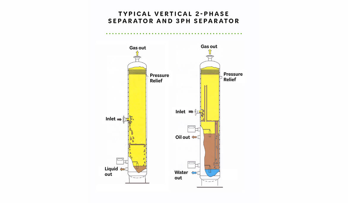
Vertical 2 and 3-Phase Separators
- < 120” diameter, 40’ S/S, < 1440 psig
-
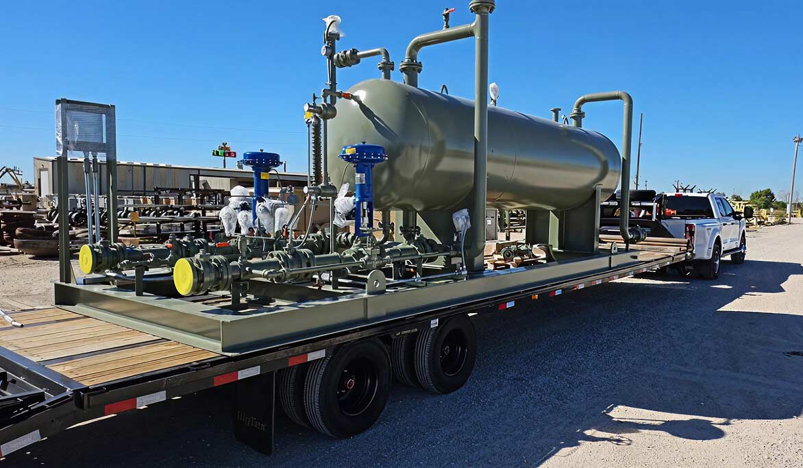
Horizontal 2 and 3-Phase Separators
- < 120” diameter, 40’ S/S, < 1440 psig
-
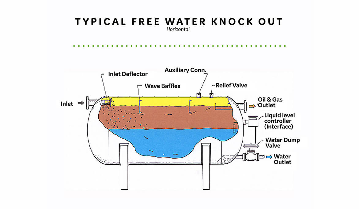
Free Water Knock Outs
- < 120” diameter, 40’ S/S, < 1440 psig
-
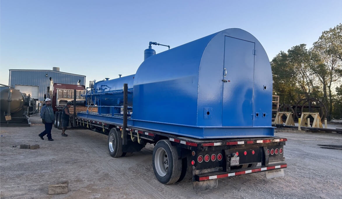
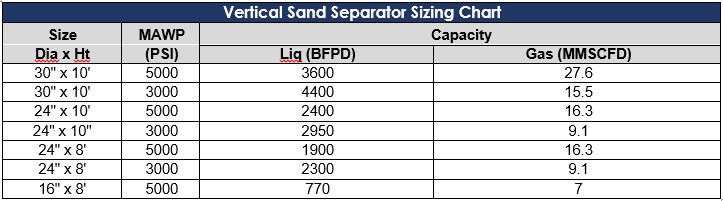
Sand Separators
- <24” OD, 10’ S/S, <5000 psig